Introduction
An oscilloscope is an indispensable tool in the world of electronics, used for visualizing electrical signals in real-time. Engineers, technicians, hobbyists, and researchers all rely on oscilloscopes to understand the behavior of electronic systems by analyzing voltage over time. This powerful tool allows users to observe waveforms, detect signal anomalies, and troubleshoot a wide range of electronic circuits.
In this article, we will explore the fundamentals of oscilloscopes, their features, types, and practical applications. We’ll also look at key specifications and how to interpret the data they provide.
What Is an Oscilloscope?
At its core, an oscilloscope is an electronic instrument that graphically displays varying voltage signals as waveforms. These waveforms represent the voltage changes in an electrical circuit over time. The oscilloscope provides valuable information about the amplitude, frequency, and phase of the signal, as well as the shape of the waveform, all of which are crucial for understanding the performance of electronic systems.
Oscilloscopes display time on the horizontal (X) axis and voltage on the vertical (Y) axis. This allows engineers to visualize how signals change over time, providing an intuitive way to understand signal behavior.
Key Features of an Oscilloscope
Oscilloscopes come with a variety of features designed to facilitate accurate measurements and analysis. Below are some of the key features of oscilloscopes:
1. Bandwidth
Bandwidth refers to the range of frequencies that an oscilloscope can accurately measure. It is one of the most critical specifications of an oscilloscope. The bandwidth is typically measured in Hertz (Hz), kilohertz (kHz), megahertz (MHz), or gigahertz (GHz), depending on the frequency range. The higher the bandwidth, the more accurately the oscilloscope can capture fast-changing signals.
For example, an oscilloscope with a bandwidth of 100 MHz is suitable for measuring signals up to 100 MHz with reasonable accuracy. If you attempt to measure a signal with a frequency higher than the oscilloscope’s bandwidth, you may not capture the signal’s full detail, leading to distorted or inaccurate waveforms.
2. Sampling Rate
The sampling rate defines how often the oscilloscope captures data points for a signal. It is measured in samples per second (S/s), and like bandwidth, it is crucial for obtaining accurate waveforms. A higher sampling rate means the oscilloscope takes more samples, producing a more detailed representation of the signal.
For example, an oscilloscope with a sampling rate of 1 GS/s (gigasamples per second) takes 1 billion samples per second. Higher sampling rates allow for more precise capture of fast signals, avoiding issues like aliasing, where signals are incorrectly represented due to insufficient sample rates.
3. Resolution
Resolution in an oscilloscope refers to the precision of the voltage measurements. It is typically measured in bits, with higher-bit oscilloscopes offering more precise measurements. For example, an 8-bit oscilloscope can differentiate between 256 levels of voltage, while a 12-bit oscilloscope can differentiate between 4,096 levels, providing greater detail in the waveform.
4. Time Base
The time base of an oscilloscope controls the horizontal scale of the display, defining how much time each division on the screen represents. Adjusting the time base allows users to zoom in or out on the waveform, observing fine details or longer trends in the signal.
5. Triggering
Triggering is an essential function in oscilloscopes that stabilizes repetitive signals for display. It helps synchronize the oscilloscope with the signal, ensuring that the waveform appears consistently on the screen. Users can set various trigger conditions, such as level, slope, or pulse width, to capture specific events in the signal.
6. Probes
Oscilloscopes use probes to connect to the circuit or device under test. Probes are designed to introduce minimal distortion to the signal while providing a clear path to the oscilloscope. There are several types of probes, including:
- Passive Probes: The most common type, used for general-purpose measurements.
- Active Probes: Used for high-frequency signals, offering better accuracy and minimal signal distortion.
- Current Probes: Used to measure current in a circuit, often for power analysis or debugging.
Types of Oscilloscopes
There are different types of oscilloscopes available, each designed for specific applications. Below are some of the most commonly used types of oscilloscopes:
1. Analog Oscilloscopes
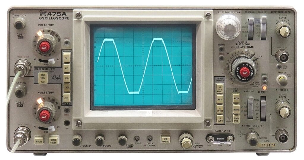
Analog oscilloscopes were the original form of oscilloscopes, using cathode-ray tube (CRT) technology to display waveforms. In an analog oscilloscope, the voltage signal directly drives the deflection of the electron beam on the CRT screen, creating a visual representation of the signal. While still in use today, analog oscilloscopes have largely been replaced by digital oscilloscopes due to their limited capabilities in capturing and storing signals.
2. Digital Oscilloscopes
Digital oscilloscopes convert analog signals into digital data using an analog-to-digital converter (ADC). This digital data can then be processed, analyzed, and stored. The vast majority of oscilloscopes used today are digital, offering a range of advanced features such as signal storage, automated measurements, and waveform analysis.
- Digital Storage Oscilloscope (DSO): A type of digital oscilloscope that stores captured signals in memory for later analysis. DSOs are popular due to their ability to capture single-shot events.
- Digital Phosphor Oscilloscope (DPO): An advanced digital oscilloscope that captures and displays signal intensity variations, offering more detailed visual representations of complex signals.
3. Mixed-Signal Oscilloscope (MSO)
A mixed-signal oscilloscope combines the features of a standard digital oscilloscope with those of a logic analyzer, allowing for the simultaneous capture of both analog and digital signals. MSOs are ideal for debugging embedded systems, where both analog and digital signals are involved.
4. PC-Based Oscilloscopes
PC-based oscilloscopes use software on a computer to control the oscilloscope hardware. These oscilloscopes are connected to a computer via USB or Ethernet, offering portability and the ability to leverage the processing power and storage of modern PCs. They are often more cost-effective than standalone oscilloscopes.
5. Handheld Oscilloscopes
Handheld oscilloscopes are portable, battery-powered devices designed for fieldwork and on-the-go troubleshooting. While they may not offer the same advanced features or high bandwidth as benchtop models, handheld oscilloscopes are ideal for situations where portability and convenience are required.
Applications of Oscilloscopes
Oscilloscopes are used in a wide range of industries and applications, including:
1. Electronics Design and Debugging
Oscilloscopes are essential for analyzing electronic circuits during the design and debugging process. They help engineers measure signal integrity, timing, and power, ensuring that components and systems perform as expected.
2. Embedded System Development
In embedded systems, oscilloscopes play a crucial role in debugging microcontroller or microprocessor-based systems. MSOs, in particular, are valuable for capturing both analog signals and digital communication protocols like I2C, SPI, or UART, which are common in embedded systems.
3. Power Analysis
Oscilloscopes are widely used for analyzing power systems. Power supply signals, such as AC mains or DC power, can be monitored to evaluate their stability, ripple, noise, and efficiency. Power-specific features, such as current probes and voltage dividers, make it easier to analyze power behavior.
4. RF and Communications
For applications involving radio frequency (RF) or communication systems, oscilloscopes help engineers analyze the modulation, noise, and frequency of RF signals. Spectrum analyzers, often integrated with oscilloscopes, allow engineers to study the frequency components of these signals in more detail.
5. Automotive and Aerospace
Oscilloscopes are indispensable in automotive and aerospace applications, where they are used to monitor sensors, control systems, and communication buses (e.g., CAN bus in vehicles). The ability to capture both high-speed and low-speed signals makes oscilloscopes invaluable for these industries.
Key Specifications to Consider
When selecting an oscilloscope for a specific application, there are several key specifications to keep in mind:
- Bandwidth: Ensure the oscilloscope has sufficient bandwidth to accurately capture the highest frequency signals in your system.
- Sampling Rate: A high sampling rate is essential for capturing fast signals and ensuring accurate waveform representation.
- Number of Channels: Depending on the complexity of the system, you may need multiple channels to capture and compare different signals simultaneously.
- Memory Depth: A larger memory depth allows for longer signal captures, which can be critical for analyzing slow-changing or complex signals.
Conclusion
Oscilloscopes are fundamental tools in the electronics industry, offering invaluable insights into the behavior of electronic signals. From basic signal visualization to complex debugging of embedded systems, oscilloscopes have a wide range of applications. Whether you’re designing electronic systems, debugging circuits, or analyzing communication protocols, a well-equipped oscilloscope can make the difference between success and failure.
Understanding the key features, types, and applications of oscilloscopes enables engineers, technicians, and hobbyists alike to harness the full potential of this powerful instrument. With ongoing advancements in technology, oscilloscopes continue to evolve, offering ever more sophisticated tools for the measurement and analysis of electronic systems.